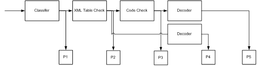
The CCC processes input signals in up to four successive steps as shown in the block diagram below, which also shows the possible signal paths. The user can select how many steps should be involved in the analysis of the signal(s) under investigation.
The possible signal paths of the CCC are shown below.
Ø The classifier attempts to classify the input signals according to their modulation formats.
Ø The table check will check the signal against the entries of an XML-formatted table.
Ø The code check will check by attempting synchronization.
Ø Finally the signal may be forwarded to a decoder for output.
The operation of the CCC is explained in detail below.
Classifier
Signal classification is done by providing the classifier with a sample of the complex values of the input signal across the chosen sampling bandwidth for a chosen sampling time and a chosen sampling rate. This sample is examined for the properties of the signals it contains. The results of the classification are output as a list of classified signal parameters.
Two classification modes are provided: a manual mode and a continuous mode. In manual mode, the classifier will make one attempt at classification. In continuous mode, the classifier cyclically classifies signals with a user selectable interval.
For more details on the operation of the classifier, refer to the section Classifier.
XML Table Check
The objective of the table check is to accelerate the determination of the mode or protocol used by the signal(s) under investigation. The signal parameters are checked against entries in a table in XML format. The file containing the table may be created and edited by the user using CCC Editor (see the section Classifier Code Check Editor). Below is a browser excerpt from the XML file with the beginning of the file and entries for two modes, VISEL and VFT-8 200 Bd displayed.
<?xml version="1.0" encoding="UTF-8" standalone="yes" ?>
-<SignalDatabase>
-<SignalList>
-<Signal Name="VISEL" Mode="visel" Modulation="FSK" Disabled="0">
<Baudrate>123.5</Baudrate>
<Shift>300</Shift>
<NumTones>2</NumTones>
<CodecheckCounter>2</CodecheckCounter>
</Signal>
-<Signal Name="VFT-8 200 Bd" Mode="no-mode" Modulation="FSK" Disabled="0">
<Baudrate>200</Baudrate>
<Shift>300</Shift>
<NumTones>2</NumTones>
<Spacing>300</Spacing>
<NumChannels>8</NumChannels>
<NumChannelsMin>2</NumChannelsMin>
</Signal>
Code Check
Code check tests whether a candidate mode can successfully synchronize to the input signal for a required number of times as specified in the corresponding entry in the XML file (<CodecheckCounter>).
Decode
In the CCC workflow P4 and P5 the corresponding decoder will be called. The signal will be decoded with all detected parameters.