Link-11 is specified under STANAG-5511 (Standardization Agreement) by NATO Standardization Agency (NSA), titled Tactical Data Exchange Link-11 / 11B.
Link-11 is an automatic high-speed HF / UHF data link exchanging picture compilation, command status and control information. Link-11B is an automatic high-speed multimedia point-to-point data link exchanging picture compilation, command status and control information. Both are also known as Tactical Digital Information Link (TADIL).
There are two types of transmission waveform: Link-11-CLEW – Conventional Link Eleven Waveform and Link-11-SLEW – Serial-tone Link Eleven Waveform.
Link-11-CLEW (Conventional Link Eleven Waveform), also known as TADIL-A, is a transmission mode used mostly in the HF band to run a tactical digital information network. This mode is specified by the US Department of Defense (DoD) in MIL-STD-188-203-1A (on 8th January 1988) and later promulgated in STANAG-5511 (on 28th February 2006).
|
Parameter |
Value |
|
Frequency range |
HF |
|
Operation modes |
Multi-carrier, DQPSK |
|
Symbol rate |
75 Bd or 45.45 Bd |
|
Modulation |
16-tone, DQPSK |
|
Receiver settings |
USB |
|
Shift/Bandwidth |
2310 Hz |
|
Center |
1650 Hz |
|
Receiver settings |
DATA, CW, LSB or USB |
|
Input format(s) |
AF, IF |
Link-11-CLEW has 16 carriers: one Doppler tone at 605 Hz; 14 data carriers starting at 935 Hz with tone distance of 110 Hz and the 16th carrier at 2915 Hz is used for data and synchronization, see table below. Except the Doppler tone, other carriers are DQPSK modulated at the symbol rate of 75 or 45.45 Baud.
Data is transmitted in two 30-bit frames, each consisting of 24 information bits and 6 error detection and correction bits (Hamming code). The information message is essentially a 48-bit word. A frame is transmitted in parallel on 15 multiplexed tones. Diversity is available as required by identical transmissions of independent side bands.
|
Number |
Frequency (Hz) |
Description |
Bit location |
|
1 |
605 |
Doppler |
- |
|
2 |
935 |
Data |
0 and 1 |
|
3 |
1045 |
Data |
2 and 3 |
|
4 |
1155 |
Data |
4 and 5 |
|
5 |
1265 |
Data |
6 and 7 |
|
6 |
1375 |
Data |
8 and 9 |
|
7 |
1485 |
Data |
10 and 11 |
|
8 |
1595 |
Data |
12 and 13 |
|
9 |
1705 |
Data |
14 and 15 |
|
10 |
1815 |
Data |
16 and 17 |
|
11 |
1925 |
Data |
18 and 19 |
|
12 |
2035 |
Data |
20 and 21 |
|
13 |
2145 |
Data |
22 and 23 |
|
14 |
2255 |
Data |
24 and 25 |
|
15 |
2365 |
Data |
26 and 27 |
|
16 |
2915 |
Data / Sync |
28 and 29 |
There are 5 frame formats:
•DNCS IM: Data Net Control Station Interrogation Message
•DNCS IWM: Interrogation with Message.
•PRM: Picket Reply Message. Picket is the switch setting of the Link-11 terminal equipment in a TDS (Tactical Data System)
•SB: Short Broadcast
•Net Test
To decode LINK-11-CLEW, choose the correct Polarity, put the Doppler Tone cursor in the FFT tuning window to the Doppler tone. Small frequency error (+/- 30 Hz) and Doppler shift will be corrected automatically and displayed in the Freq Err/Doppler Shift field. The data is displayed in the main text window. Because the mode transmits link information, the data is displayed in a 30-bit group hex.
The frame format is displayed together with the baudrate in the Format field. Confidence shows the decoding quality: a value over 95 means the FEC has probably corrected all bit errors, the data decoded is mostly reliable.
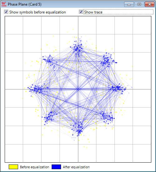
Link-11-SLEW is a transmission mode with a single carrier (at 1800 Hz) modulated by QPSK data symbol at a rate of 2400 baud.
|
Parameter |
Value |
|
Frequency range |
HF |
|
Operation modes |
Single-carrier, QPSK |
|
Symbol rate |
2400 Bd |
|
Modulation |
QPSK |
|
Receiver settings |
USB |
|
Shift/Bandwidth |
2600 Hz |
|
Center |
1800 Hz (carrier frequency) |
|
Receiver settings |
DATA, CW, LSB or USB |
|
Input format(s) |
AF, IF |
The SLEW waveform transmission format consists of an acquisition preamble followed by two or more fields. Each field is followed by a reinsertion probe. The first field follows immediately after the preamble. The first field is the header field and contains information that is used by the Combat Data System (CDS) and the encryption device. If a PU (Participating Unit) has data to transmit, successive data fields follow the reinsertion probe of the preceding fields. These data fields consist of track data and other user data. The last field to be transmitted is the end-of-message (EOM) field. The transmission ends with a reinsertion probe.

The preamble is 80 ms long, it consists of a 192 tri-bit known sequence generated from a pseudo random code.
The reinsertion probe (7.92 ms) contains a known sequence of 19 tri-bits (all zero) symbols and shifted by a scrambler. The probe is inserted between fields and used by a receiving PU to track the channel conditions, thus permitting adjustments to coefficients within the adaptive equalizer.
A field contains a data sequence conveying information originating from either CDS or the Data Terminal (DT). The data from these sources are accommodated using three different types of fields. These are the header field, the CDS data field and the EOM field. Each field is 18.75 ms long and consists of 45 QPSK symbols (90 bits). The 90-bit sequence consists of 78 data bits and 12 CRC bits for error detection. The 78 data bits are the output of a Full Tail Biting Convolutional Block Encoder (FTBCB) at the rate of 1/2 (for header field) or 2/3 (for data field).
There are two SLEW transmission types.

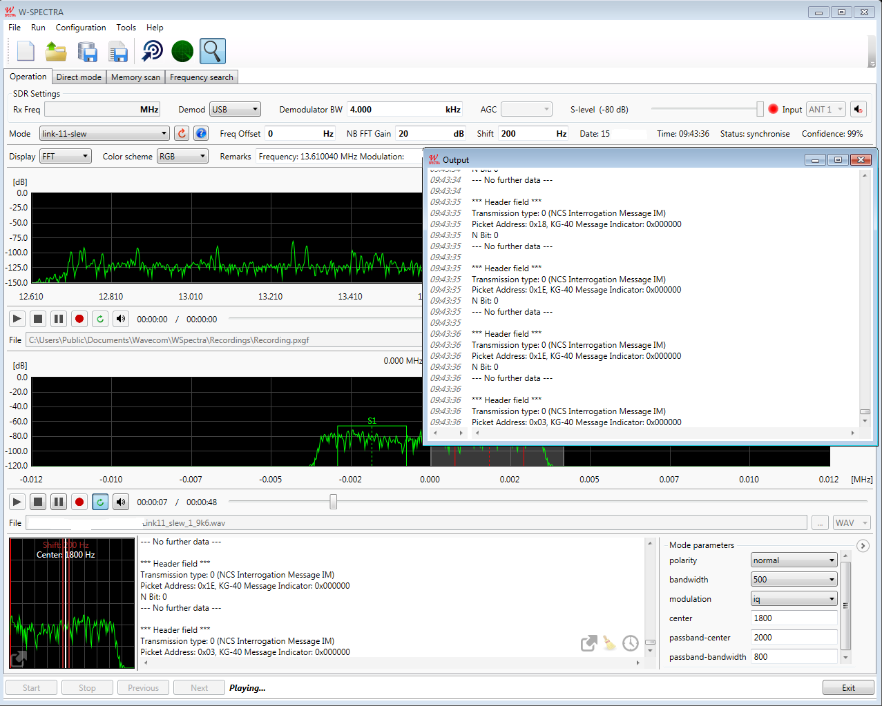
The first type of transmission is the NCS (Net Control Station) Interrogation Message (IM). This transmission is only initiated by the NCS. It comprises a preamble and a header fields. The transmission does not include any CDS data fields or an EOM field. The second type of transmission is the NCS IWM (NCS Interrogation with Message) or picket reply message. This type of transmission can be initiated by either the NCS or a picket. It comprises a preamble, one header field, several CDS data fields and an EOM field. In NCS IWM the tripplet – header, data and EOM – can appear directly after a reinsertion probe, without a new preamble.
To decode LINK-11-SLEW, choose the correct Polarity, set the correct Center using the FFT tuning window. Frequency error (+/- 80 Hz) will be corrected automatically and the true signal center will be displayed in the Carrier field. The data will be displayed in the main text window. Frames with CRC error will be displayed in red.
Confidence shows the decoding quality: a value over 95 means the FEC has probably corrected all bit errors, the data decoded is mostly reliable.
